-
Home
- Company
- Services
-
Products
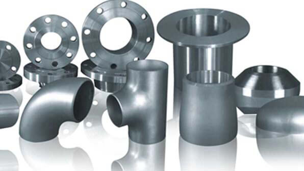
- Piping Material
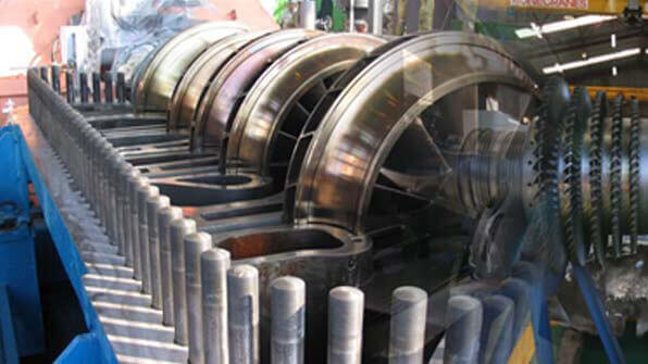
- Machinery
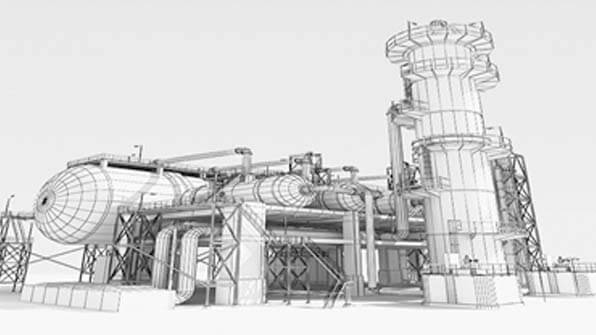
- Fixed Equipment
- Drilling
- Instrument & Control
- Catalyst & Chemicals
- Market-specific Solutions
- Projects
- Worldwide & Partners
- Media Center